DIFFERENTIAL PAIRS
Introduction
Differential signalling sends equal-and-opposite currents on two closely-spaced traces. Tight coupling keeps the fields local, reduces susceptibility to noise, and controls differential impedance. Any difference in electrical length between the two traces is skew; too much skew narrows the sampling window at the receiver. During routing, corners, detours, and layer transitions are the usual sources of skew, so the layout process focuses on:
- maintaining a consistent pair spacing on the coupled portions,
- correcting skew soon after it’s created, and
- limiting the distance and separation over which the pair is uncoupled.
Proteus supports differential-pair routing with an assisted mode and applies phase-matching after you complete the route or when you request it; route direction matters because matching is applied from source to receiver.
The commands for differential pairs sit in a High Speed Design submenu on the track context menu, alongside the length matching commands. The pair-specific entries are Phase-match diff. pair, Display phase-offset and Remove phase-match serp., together with Reverse route direction, Match route lengths, Input target length and Remove length matching.
Note on impedance: specify the pair width and gap to meet your target differential impedance per your stackup or fabricator guidance. The pages here describe enforcing your chosen geometry and tolerances. This division of labour follows the high speed design guidance of IPC-2251: the impedance target comes from the interface specification and the fabricator, while the layout system enforces the chosen geometry.
Setup
In Proteus a differential pair is defined on the schematic and then configured on the layout before routing. Specifically, on the schematic we need to know the component pin names of the differential pair pins and we also need each differential pair to have a unique name or identifier. We then need to configure a net class for the differential pair, set some specific clearances and set up a couple of design rules before we begin routing.
This is discussed in a dedicated topic linked below.
See Also:
Routing
Once the setup is complete we can now route the differential pair. Proteus includes a dedicated routing mode for differential pairs which, depending on the routing problem, will be used for all or some of the routing task. The most important thing to remember is that you can route in either differential pair or standard mode. Regardless of how the two routes get completed Proteus can detect the completion of the differential pair when the connections between the pins are complete and will then perform any required phase matching.
Indeed, for all but the simplest of routing scenarios, the designer is going to have to help with the routing problem. For example, with a BGA normal routing mode would be used to fanout to stub vias on both sides. The assisted diff pair routing mode can then be used to route between the two sets of vias.
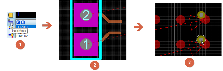
Organise the fanout at both sides in normal routing mode.
Next, switch to diff pair mode, select the routing layer and then click on a track or via on the fanout from the source device to pick up the diff pair. Route as normal to the destination/receiver and click on one of the fanout stubs at the other side to complete.

Pick up the pair from a fanout via and route across to the stubs at the receiver.
The Pre-production Check will test all differential pairs and warn you if they are not compliant with the configuration. You can also generate a detailed differential pair report at any time via the Project Notes module.
Routing Checklist
1. Place components first
Make sure all relevant parts (including pass-through devices such as AC-coupling capacitors, common mode chokes, etc) are on the schematic and board.
2. Configure pairs in the schematic
Use the Differential Pair Configurator on the schematic to declare which nets are paired and to define passthrough components. This ensures the pair is treated as continuous through series devices.
3. Set rules in the layout before routing
In PCB Layout, assign the pair to a net class for track width and via style, and then use the Differential Pairs tab of the Design Rule Manager to set the pair spacing under Clearances and the skew and unpaired length limits under Tolerances. These values control assisted routing and compliance checks.
4. Fanout manually
Route fanouts at the pins manually before switching to diff-pair mode. Keep vias and pad entries symmetrical.
If the pair passes through a series component (such as an AC-coupling capacitor), you will usually need four fanouts: two at the input side of the device and two at the output side.
5. Route the pair in diff-pair mode
Switch to diff-pair routing mode for the main run. Proteus will route both lines together and apply automatic skew correction when the route is committed, including across defined passthroughs.
Where a passthrough device splits the route, you will complete the pair in two routing passes: one up to the component, and another from the component onward.
6. Manage layer changes carefully
When changing layers, use identical vias for both lines and place them symmetrically. Add nearby stitching vias if the reference plane changes, to maintain a continuous return path.
Note that SPACE is deliberately inert while you are routing a differential pair: it does not drop a via, as it would in normal routing mode. Route the fanout vias in normal routing mode first, then pick the pair up from them.
7. Avoid long unpaired segments
Short uncoupled regions at pads or through fanouts are expected, but keep them as short as possible. The unpaired distance and separation are tracked in Proteus reports and checked at pre-production.
8. Handle branch stubs with care
Proteus ignores stub length when assessing differential-pair compliance, but electrically long stubs still degrade performance. Keep any branch connections short, or place passives inline if possible.
9. Verify with reports and checks
After routing, review the differential-pair report and run the Pre-Production Checker. These tools highlight any pairs outside tolerance for length, separation, or unpaired distance.
10. Impedance geometry
Proteus enforces the pair width and separation you specify but does not calculate impedance. Obtain the required values from your stackup or fabricator and apply them through the net class and differential-pair settings.
Review the setup page to cover schematic and layout configuration
Review the examples page for practical walkthroughs.
Troubleshooting
It would be very helpful for us to see real world situations where the assisted routing (both tracks at once) fails. If you come across this and are able to submit your board to [email protected] it would be much appreciated and will help us improve the routing algorithm.
If you find yourself in a situation where you have set off routing and cannot finish at the end point, and get something like:
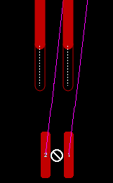
The pair will not complete at the end pads.
This will be because the DRC rules are preventing the tracks from connecting to the end pads. You will need to either set the track thickness to be smaller in the Net Classes tab of the DRC form, or change the Pad-Trace DRC rule for your Diff pair net Class.
A good indication that this is the case is that the ghost tracks and arrow do not appear:

No ghost tracks and no arrow, so the pair cannot terminate here.
it should look like:
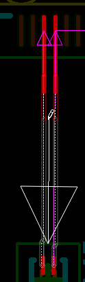
With the design rules corrected the ghost tracks and arrow appear.
See Also:
Example: Routing a simple differential pair on one layer.
Example: Routing a differential pair with vias / fanout.
Example: Routing a differential pair through a passive component.
Example: Routing a differential pair with taps / branches to passives.
Example: Routing a differential pair in manual routing mode
Phase Matching
Phase Matching (sometimes called skew correction) is needed where the lengths of the two tracks differs beyond the specified tolerance. This means that the equal and opposite differential signal is likely to be no longer opposite and so corrective action is needed. Almost all of the time, the track lengths drift due to cornering and the corrective action is a short serpentine on the shorter track after the corner is complete.
Regardless of how you route the diff pair you can phase match it when it is complete. If you use the assisted routing mode the phase matching will happen automatically when you complete the route. If you complete manually then you can phase match with High Speed Design > Phase-match diff. pair on the track context menu. Regardless of how it happens it's important to understand that phase matching depends on signal direction.
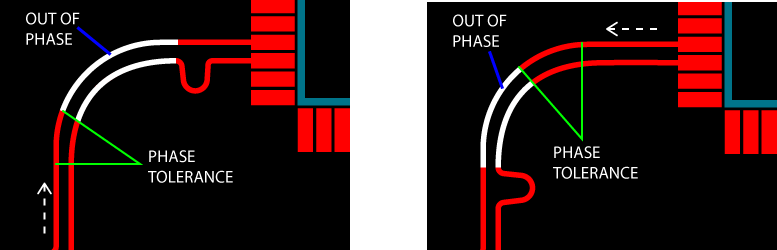
The direction of travel during routing determines where serpentine segments are used to equalise the trace lengths.
It is assumed that you are routing from source to destination and the phase matching takes place accordingly. If this is not true and you have routed from destination to source you can reverse the route with High Speed Design > Reverse route direction on the track context menu. This will automatically re-calculate the phase matching to be correct for the new direction of travel.
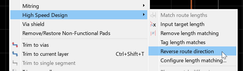
Reverse the direction of the differential pair.
The direction currently in force is normally fairly obvious by looking at which end of the corner the corrective serpentine segments occur but it is also indicated in the differential pair report.
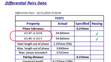
The differential Pair report includes indication of which component is deemed the source.
Visualising Phase
Probably the easiest way to analyse the phase situation on the differential pair is to use High Speed Design > Display phase-offset on the track context menu for the differential pair.
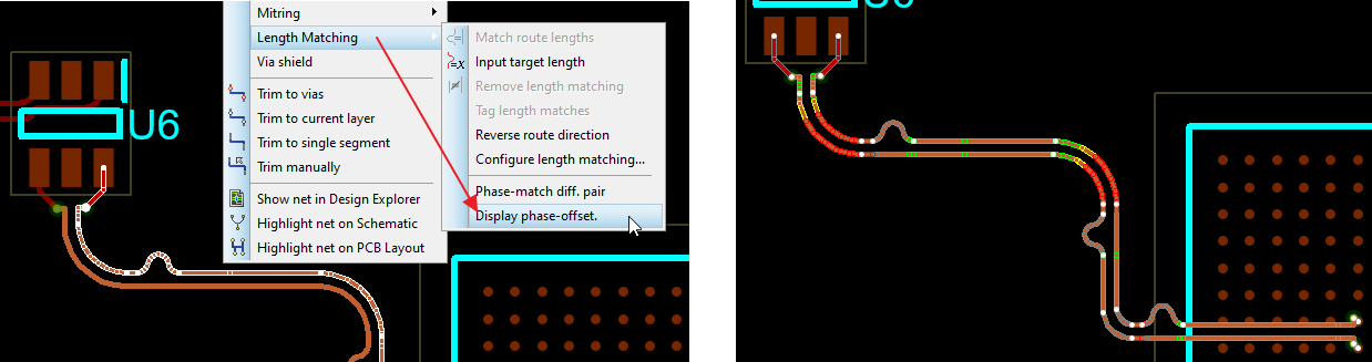
Display phase-offset outlines each segment of the pair according to its phase status.
Green outlined segments are in phase (signals 180 degrees offset), yellow segments are out of phase but inside tolerance (acceptably skewed) and red segments are skewed beyond the phase tolerance. You'll notice corrective serpentines take place on the straight segment immediately following red segments to minimise out of phase distance. Click anywhere in free space to remove the visualisation.
You can use this visualisation together with the reporting to refine or tune the diff pair. You may need to adjust parameters or re-route using a slightly different topology.
If you would rather have the phase correction gathered at the end of the route than spread over several serpentines in the middle of the tracks, open the Design Rule Manager from the Technology Menu, switch to the Differential Pairs tab and tick Correct phase shift at end. The field is described with the rest of the tab in Differential Pair Setup.

Tick Correct phase shift at end to gather the phase correction at the end of the route.
Length Match the Pair
You can set a target length for differential pairs in much the same way as normal tracks, namely with High Speed Design > Input target length on the track context menu.
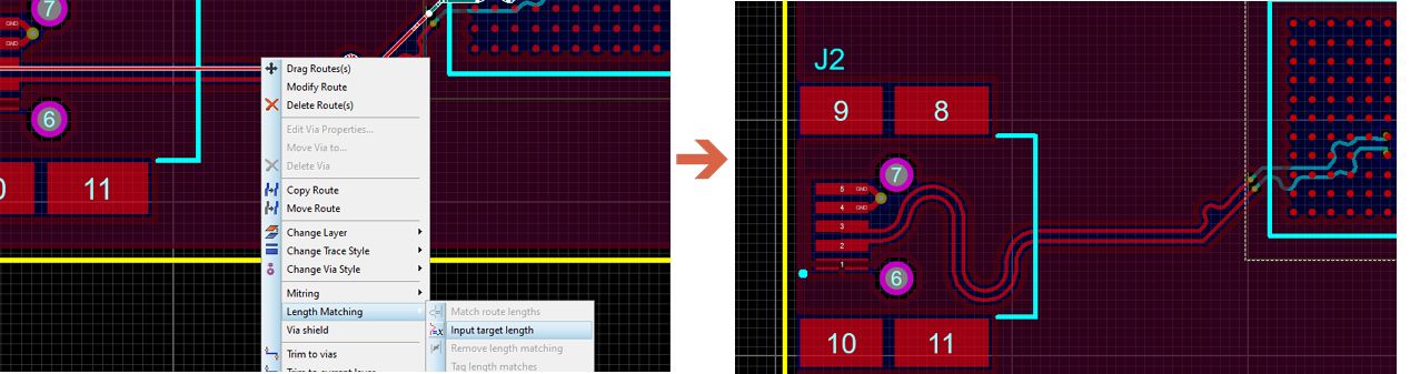
Diff Pair Length Matching will lengthen both tracks to the target length with serpentine segments as shown above.
Similarly, you can match the length of two differential pairs by selecting one track on each pair and then using High Speed Design > Match route lengths from the context menu.
You can click on either one of the tracks on a length matched serpentine and then drag the serpentines along the route to a position of your choice. This works exactly the same as for 'single track' length matched serpentines.
See Also
Example: Length Matching a Differential Pair
Length Matching vs Phase Matching
After length matching the differential pair the automatic phase matching will be applied. Since this can of itself add length your differential pair may end up outside length match tolerance. You can check all of the tolerances via the diff pair report at any time. If this happens and you want to make changes there are a couple of things you can do.
1) Review the routing topology. Phase matching is required normally when the differential pair routing corners. Removing unnecessary cornering will reduce the amount of phase matching required.
2) Review the tolerances. It might be that you can relax the phase match tolerances such that phase matching is not required after length matching. This in turn will help keep the length matching inside tolerance.
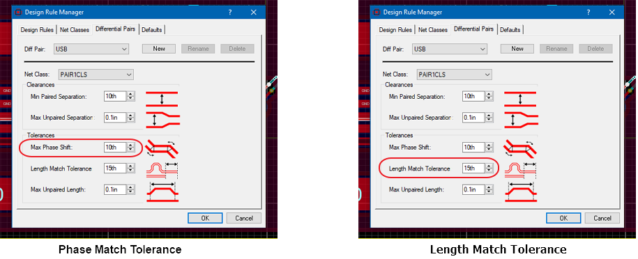
Adjust the tolerances from the differential pair tab of the Design Rule Manager (Technology Menu).
3) Review the length matching settings. Phase matching serpentines will not be placed inside a length match serpentine. It is therefore often better to have smaller length match serpentines (more of an 's' shape than a 'u' shape) so that you don't have a long straight segment of track that is out of phase. All of the length matching options are available with the Technology Menu > Configure Length Matching command, which opens a three tab dialogue. The Length Matching tab governs ordinary routes, the Differential Pair Length Matching tab governs the serpentines added when a pair is tuned to a length, and the Differential Pair Phase Matching tab governs the shape and size of the much smaller serpentines used for phase correction. If phase matching is adding more length than you can afford, the third tab is where you constrain it.

Changing the Length Tuning settings can have a big impact on the routing and also the amount of track that is out of phase.
If you want to start the length matching again after making configuration changes you should first select High Speed Design > Remove length matching from the context menu on either of the tracks. After the existing length matching is removed you can length match again with the new tolerances.
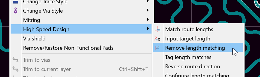
Remove existing length matching from the diff pair before trying again with new tolerances.
4) Remove an individual phase-matching serpentine. Where a single serpentine is in the wrong place, hover the cursor over it and use High Speed Design > Remove phase-match serp. on the track context menu. This deletes just the serpentine under the cursor and leaves the rest of the pair alone, so it is the surgical alternative to removing all of the length matching and starting again.
You can use Display phase-offset on the context menu at any time to see over what distance the diff pair is out of phase.
In the end, much will depend on the application. Since phase matching occurs automatically after both route completion and a length matching operation it has priority over the target length being set. The steps above outline what you can do to change this behaviour (e.g. make phase tolerance big) should you find for example that absolute length is more important in your application.
Differential Pair Reporting
Creating/Opening the Report
The differential pair report provides valuable data on the routed pair along with a compliance check against specified parameters. To launch the report you first open the Project Notes tab and then select the report from the list of templates.
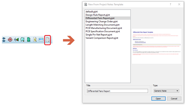
Creating a new Diff Pair Report in Project Notes.
Alternatively, if you have another report already loaded in Project Notes you simply add the differential pair report via the file menu command.
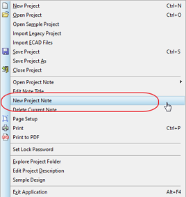
Create a new report from File Menu in Project Notes.
Finally, you can also insert the differential pair table to a custom report via the Project Data button at the top of the Project Notes module.
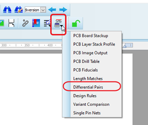
Add the Differential Pair data object to an existing report.
The report itself comes from a basic Labcenter template and so we've included quite a bit of explanatory text and prompts for user input. You should edit/modify to your corporate standards and then save as template (Template menu) so that future reports are based on your own templates.
Report Data
The data table contains information about each differential pair along with a compliance status column on appropriate fields.
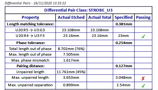
Example Differential Pair Report Table in Project Notes.
Note that the rows containing the route lengths also indicate the direction of the route (source pin -> receiver pin). This is normally taken from the way in which the tracks were routed but is easily changed with High Speed Design > Reverse route direction on the track context menu. This is always worth checking as the direction is important for all phase matching calculations.
Also note that both the etched distance (tracking only) and the total distance are displayed in different columns. There are three factors which can contribute to the length of a diff pair:
- The tracked / etched length.
- Any specified internal length of the pins.
- The distance between the pins of any pass through components on the PCB.
The system will calculate 1 and 3 automatically and you can add internal pin lengths yourself with the Add Internal Lengths command on the pad context menu.
See Also:
Routing with Pass Through Components.
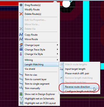
Reverse the Route direction to ensure source to receiver in the report.
Each report is time-stamped and does not update as changes are made to the layout. You can update a particular data table from the right click context menu on the table. In the case of a custom report where you have multiple data objects (e.g. Diff Pair Data, Length Match Data, Stackup Data) you can update the entire report from the Reload Project Report command on the Edit Menu.
Length Matching Tolerance
The first row of the table repeats the Length Match Tolerance set for the differential pair class in the Design Rule Manager. It is the window within which the pair as a whole must match its target length, or the length of another pair, and it is the figure against which the route length rows immediately below it are judged. It has nothing to do with the matching of the two tracks in the pair to each other, which is governed by the phase tolerance.
Setting the Length Match Tolerance
Phase Tolerance
This is the allowable difference in track length due to length mismatch (e.g. a corner) before we are considered out of phase. Serpentine routing is applied at the end of a corner to equalise the track lengths when we are deemed to have drifted out of phase.
It's important to note that serpentine routing for phase matching can only be applied at the end of a corner. This means that a long corner (e.g. a large curve) can create a significant distance before serpentine routing is applied.
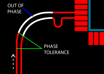
Despite a difference in length as we corner the two tracks are not out of phase until they exceed the phase tolerance.
Be aware that phase matching depends on the direction of the route. You may need to use Reverse route direction from the context menu; see phase matching for more information.
You can see phase tolerance as yellow segments using the Display phase-offset command.
Total Length Out of Phase
The total distance over which the two tracks are deemed to be out of phase according to the phase tolerance. Unlike the unpaired length here we are considering tracks which are obeying the pairing distance. We are measuring the length over which these tracks differ in distance from the source pad(s).
The source pads are determined by the routing direction (src->dst) and are indicated by the pin descriptions in the table. You can use Reverse route direction from the right click context menu on one of the tracks on the layout if you have routed from dst -> src.
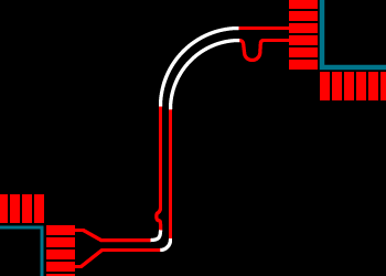
All coupled, out of phase segments
Distance out of phase is shown as red segments using the Display phase-offset context menu command.
Max Length Out of Phase
This is the maximum contiguous paired length that the two tracks are deemed to be out of phase according to the phase tolerance. It doesn't include serpentines or segments where the track separation exceeds the paired distance.
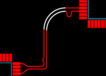
Largest length out of phase
Max Phase Mismatch
This is an indicator of the worst case scenario and provides the largest distance that the two tracks deviate by over the course of the route.
Pairing Distance
This is the default and also preferred separation of the two tracks, taken from the Min Paired Separation value set in the Design Rule Manager. Proteus allows one thou of latitude on it, so the tracks are still counted as paired where the separation exceeds the minimum paired separation by up to one thou. Beyond that they are treated as unpaired.
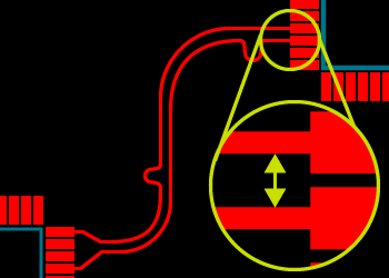
The pairing distance is the separation at which the two tracks are considered coupled.
Unpaired Length
This is the total distance over which the two tracks are spaced at a distance greater than the pairing distance. It is the cumulation of all the unpaired segments of the route.
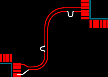
Unpaired length is the sum of all the segments spaced wider than the pairing distance.
Max Unpaired Length
The maximum distance that the tracks are unpaired for in the route. The actual value reported is the longer of the two lengths of track over which the separation exceeds the pairing distance.
Unpaired length generally results from serpentine segments used to equalise the track lengths. To correct an overly large reported unpaired length you need therefore to look at the corners during routing (causing the length mismatches) and/or the max unpaired separation specification (influencing the distance that the tracks are unpaired for).
It can also result from fanout from the source/receiver pins, covering the etched track distance used to get from the two pins into a paired state. Generally this is routed manually by the user and is unavoidable.
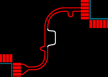
Longest section of unpaired trace
Max Unpaired Separation
This is the maximum space between the two tracks that occurs when the two tracks are not honouring the pairing distance.
While the specified value will be enforced for serpentine segments note that the actual maximum may well be due to an unavoidable fanout or termination routing which you have placed manually.
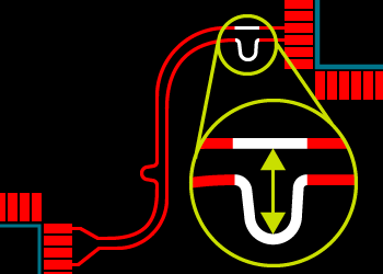
Largest distance allowed between two traces
Pair Not Valid
Where the report shows a Pair Not Valid row in place of the usual measurements, Proteus has been unable to resolve the declared pair into two complete routes. The usual causes are that one or both lines are unrouted or only partly routed, that the schematic side configuration is incomplete so the signal path does not reach from start pins to end pins, or that a pass-through component on the line has not been declared. Complete the routing or revisit the configuration and the pair will report normally.
See Also: